VB Cartridges:
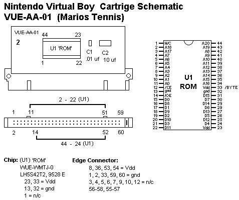
VUE-AA-01 (2)
U1 ROM: Toshiba TC538200AFT
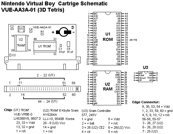
VUE-AA3A-01 (3)
U1 ROM: Toshiba TC538200AFT
U2 RAM: Cypress CY6264
Reprogramable Cartridge Schematics
vb_cart.pdf, 32_pin_cart.pdf and 4x_pin_cart.pdf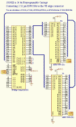
32Pin EPROM
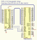
40 pin EPROM
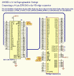
44pin EPROM
Game Controller/Power Adapter, and Link Port
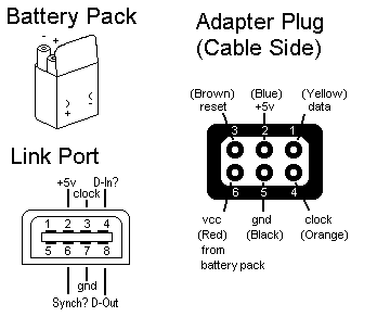
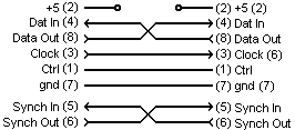
Link Cable
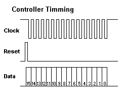
Notes: On the controller, Reset goes
High then the first controller bit is pushed out (before the first tick
of the clock), everything is latched on the rising edge. Also the
bits are inverted a High value means no button was pushed. Bit1 should
always be low (a logical 1) and Bit0 is the battery status bit, it should
be ignored. I think the controller is powered from pin2 even though
pin6 is the power from the batteries, and I don't think it is necessary
to switch the controller on to get it to work?
On the Link Port: The idea is
that both VB's transmit a steady 'synch' pulse out on pin 6 with a
20 ms period, and they use these pulses to sync the transmit and receive
data for a crude form of flow control. There is a Master and a slave
unit the master transmits the clock that all communications is synched to.
And there is a control line that can be used to notify the receiving VB
that data is waiting. The default clock on the link port runs with
a 20 µs period, so a 8 byte transmit takes 160 µs total.
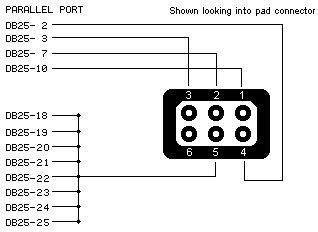
Hooking up a VB Controller to the Parallel Port sent in by Gravis Zero. Take a look at this doc VB to Parallel Port adapter for more details.
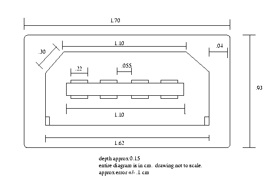
VBLink Dimensions by Adam Hunter
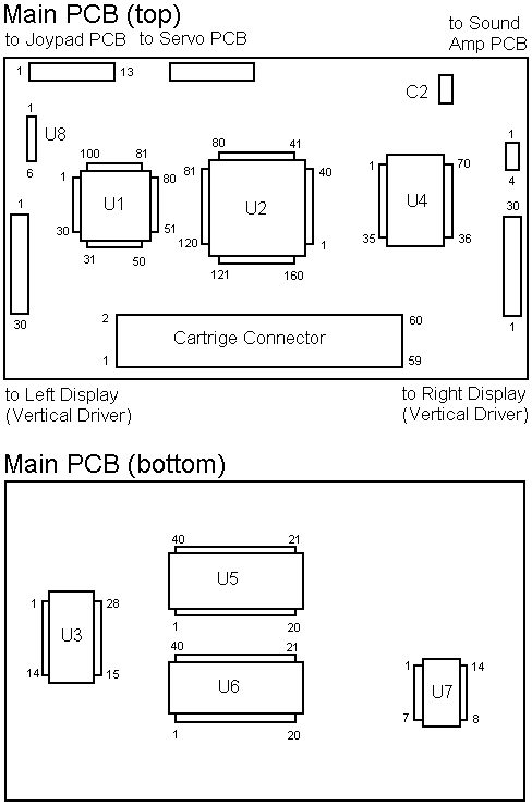
VB Main PCB
VB Servo PCB/VB Sound Amp PCB
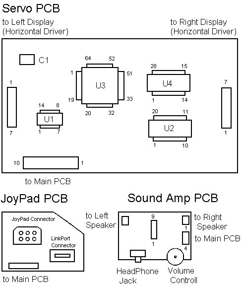
VB Chip List
Main Board
U1: Nintendo NVC-VUE, (C) NEC '91 '93 9520KX003, 100pin (120?)
U2: Nintendo '95 VUE-VPU, 9516KK015, 160pin
U3: Nintendo '95 VSU-VUE ATT, 9521A3001, 28pin
U4: Nintendo VRM-VUE, 9524KU003, 70pin
U5: Toshiba TC511664BJ-80, 9417HBK, 40pin 1mByte D-Ram (EDO?) 1mb x 8
U6: )(Link LH5P1632N-70Y, H51804B, 40pin 512kByte PSram 512k x 8
U7: Texas Instrument 57AOY5K, HCU04, 14pin Hex Inverter? (57AHCU04)
U8: DC-DC Transformer, 6pin
C2: D200f5, 20mHz Crystal?
Sound Amp PCB
U1: M 525, mm1030B, 9pin Stereo Amp?
Servo PCB
U1: JRC 2901, A511A4, 14pin
U2: T9450H, 74AC240, 20pin Octal inverter/line driver?
U3: Nintendo '95 SCG-VUE ATT 044, 951SWK018, 64pin
U4: Nintendo '95 SCM-VUE ATT, 9515C3031, 28pin
C1: TXC 8.00 20, 8Mhz Crystal?
As a final thought to open a VB it is necessary to notch a flathead screwdriver to fit over the security screws on the VB. There are two sizes (one on the VB and one on the cartridge) so two screw drivers will be necessary.
